


You’ve got an awesome model… and then you load it into your slicer and realize the obvious problem: it doesn’t fit.
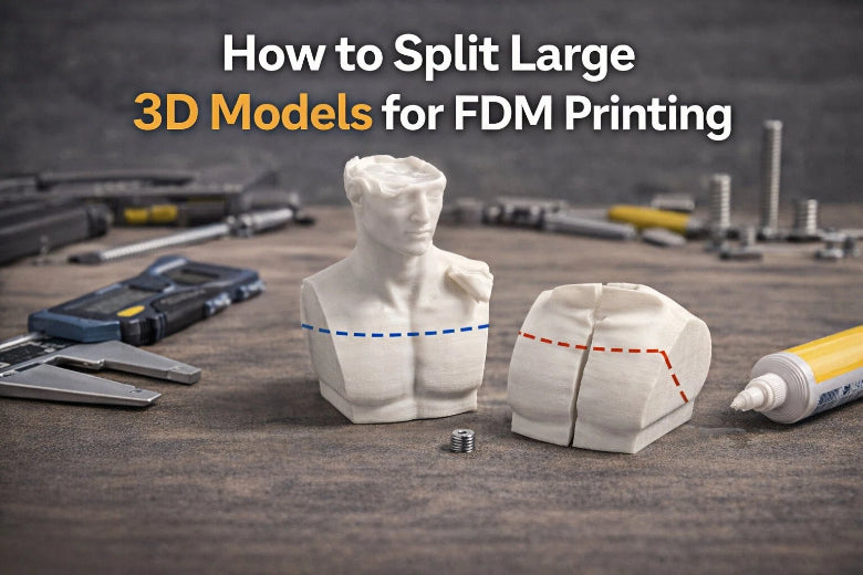
Splitting a large model into smaller sections is a normal part of FDM life—especially for cosplay props, big enclosures, signs, and classroom projects. The trick is doing it in a way that (1) prints reliably, (2) goes back together accurately, and (3) doesn’t leave you with a seam that looks like a crack.
This guide walks you through the whole workflow: planning the cut, splitting in common slicers, adding alignment features, printing for easy assembly, and finishing.
How to split large 3D models without ugly seams
Before you touch any “Cut” button, take 2 minutes to plan your seams.
Step 1: Plan your cut lines (this matters more than the tool)
Before you touch any “Cut” button, take 2 minutes to plan your seams.
Put seams where the eye expects them
Good places to hide seams:
- Along sharp edges (corners, panel lines, bevels)
- Under raised details (ridges, trim, text)
- On the back side (display-facing vs hidden-facing)
Avoid seams across:
- Smooth curved “hero” surfaces (helmets, faces, domes)
- Fine surface textures you don’t want to re-sculpt after sanding
Don’t split across the weakest direction
FDM parts are weakest between layers. If your joint will be stressed (a handle, bracket, cosplay armor strap point), try to:
- Orient each piece so the layers resist the real-world load, and
- Avoid a cut that creates a thin “lip” that can snap.
Step 2: Choose your splitting method (slicer vs mesh/CAD)
There are two common ways to split an STL for 3D printing:
Option A: Split in your slicer (fastest for most prints)
Use your slicer’s cut tool when:
- You just need a clean planar cut
- You want quick connectors (pins, plugs, dovetails)
- You’re not redesigning the part—just making it printable
Option B: Split in Meshmixer/Blender/CAD (best for complex joints)
Use modeling tools when:
- You need a custom joint shape (tongue-and-groove, complex keys)
- You want to add internal channels, screw bosses, or reinforcement features
- The STL is messy and needs repair before/after cutting
If you’re printing for a maker space or classroom, slicer-based splitting is usually the most repeatable workflow for new users.
Step 3: Split the model in PrusaSlicer (planar cut + connectors)
PrusaSlicer’s Cut tool supports planar cuts, a dovetail mode, and multiple connector types. If you want the exact UI behavior and connector options straight from the source, Prusa documents it here (2025): PrusaSlicer Cut tool documentation.
3.1 Make the cut
- Import your model.
- Select it on the plate.
- Open the Cut tool (Prusa notes you can press C).
- Position the cut plane.
- Choose whether you want to keep both sides as separate objects.
3.2 Add connectors (so the parts self-align)
If you want the joint to “click into place” during assembly, use connectors (alignment pins, plugs, or dowels depending on your workflow):
- Dowel: creates sockets on both sides and generates a separate pin/connector to print.
- Plug: makes a male feature on one side and a matching socket on the other.
- Snap: creates a snap-fit (useful for some enclosures; not ideal for heavy sanding/painting workflows).
Key Takeaway: For large aesthetic prints (props, display pieces), a dowel-style alignment pin is usually the simplest way to keep seams tight and repeatable.
Step 4: Split the model in Bambu Studio (planar + dovetail)
Bambu Studio also offers planar cuts, a dovetail mode, and connectors. The official overview is here: Bambu Studio Cut tool documentation.
4.1 When to use dovetail mode
Dovetails can be great when you want:
- Stronger mechanical alignment than a simple flat seam
- A joint that resists shifting while you clamp/glue
Bambu’s documentation notes that dovetail parameters like Depth, Width, Flap Angle, and Groove Angle affect the fit and strength.
4.2 Watch for geometry issues
After a dovetail cut, you may get a prompt to fix non-manifold edges. Don’t ignore it—non-manifold geometry can turn into slicing artifacts later.
Step 5: Pick the right alignment strategy
If you remember one thing, make it this: flat seams drift. Even if you’re careful, glue is slippery and clamps pull parts around.
Here are practical alignment options (from simplest to most “locked in”):
Flat seam only (fast, but least forgiving)
Use it when:
- The seam is hidden
- The part isn’t load-bearing
- You can clamp against a flat reference surface
Dowels / pins (best default)
Use dowels when:
- You want repeatable alignment
- You want to dry-fit quickly
- You’re teaching new users a reliable workflow
Plugs (simple, but watch thin walls)
Plugs are convenient, but they can weaken thin shells if the plug eats too much wall thickness.
Dovetail joints (great for big panels and functional parts)
Dovetails work well when:
- The seam is long
- You need shear resistance
- You can tune the fit so it assembles cleanly without forcing
Snap fits (nice in some enclosures; not ideal for heavy finishing)
Snap joints can be great for serviceable parts, but they’re often a bad match for prop finishing where you’ll sand, fill, and paint.
Step 6: Print settings that make assembly easier
Minimize “elephant’s foot”
A slightly flared first layer can throw off alignment, especially on flat seams.
- Consider a small chamfer on edges if you’re modeling the joint in CAD.
- If you’re using slicer cuts, make sure your first-layer settings are dialed in and your Z-offset isn’t squishing too hard.
Use a brim when parts are tall or narrow
If a split creates a tall thin piece, a brim can prevent a late-stage tip-over.
Orient for strength (not just for supports)
If the assembled part will be stressed:
- Rotate each section so the layer lines are not the failure plane.
- Avoid long “vertical” seams in parts that will be bent or twisted.
Step 7: Assemble without panic (dry-fit first)
A repeatable assembly routine saves you from misalignment and gaps.
- Clean up: remove strings and blobs on the seam faces.
- Dry-fit: assemble with no glue and check that connectors seat fully.
- Lightly sand high spots on seam faces.
- Glue in stages: don’t try to assemble a 6-part model all at once.
- Clamp carefully: clamping pressure can twist thin parts out of alignment.
If you’re reinforcing a functional print, consider:
- Printing internal dowels/connectors thicker (when possible)
- Adding mechanical reinforcement in CAD for load-bearing parts.
Step 8: Hide the seam (if the model needs to look like one piece)
For cosmetic projects, seam hiding is usually:
- Sand the seam flush.
- Use a filler (filler primer, spot putty, or epoxy filler depending on your finishing process).
- Wet sand to blend.
- Prime and paint.
This is where seam placement pays off. A seam on a sharp edge is 10× easier to disguise than a seam across a smooth curve.
Troubleshooting: common failures and fixes
The parts don’t line up (offset seam)
- Add dowels/plugs/dovetails instead of relying on a flat seam.
- Check for elephant’s foot on the seam faces.
- Dry-fit before glue.
The seam has a visible gap
- Your cut line may be landing on a curved surface that’s hard to clamp.
- Try splitting along a corner/edge.
- Add more alignment features spaced farther apart.
The joint is weak
- Re-orient the pieces so layers aren’t the failure plane.
- Use a joint style that increases surface area (dovetail or keyed seam).
- Add internal reinforcement in CAD for load-bearing parts.
FAQ
Is it better to split a model in the slicer or in CAD?
If you need a simple cut with good alignment, slicer tools are faster. If you need custom joints, reinforcement, or design changes, CAD/Blender/Meshmixer is worth the extra time.
What’s the easiest way to keep parts aligned during gluing?
Use alignment features (dowels/plugs/dovetails), dry-fit first, and glue in stages.
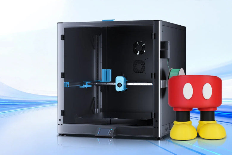
Should I split a model—or buy/print on a bigger printer?
If you split occasionally, splitting is fine. If you split constantly, the time you spend on seams adds up.
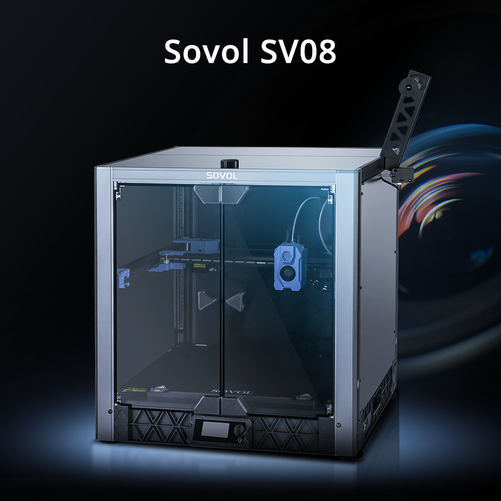
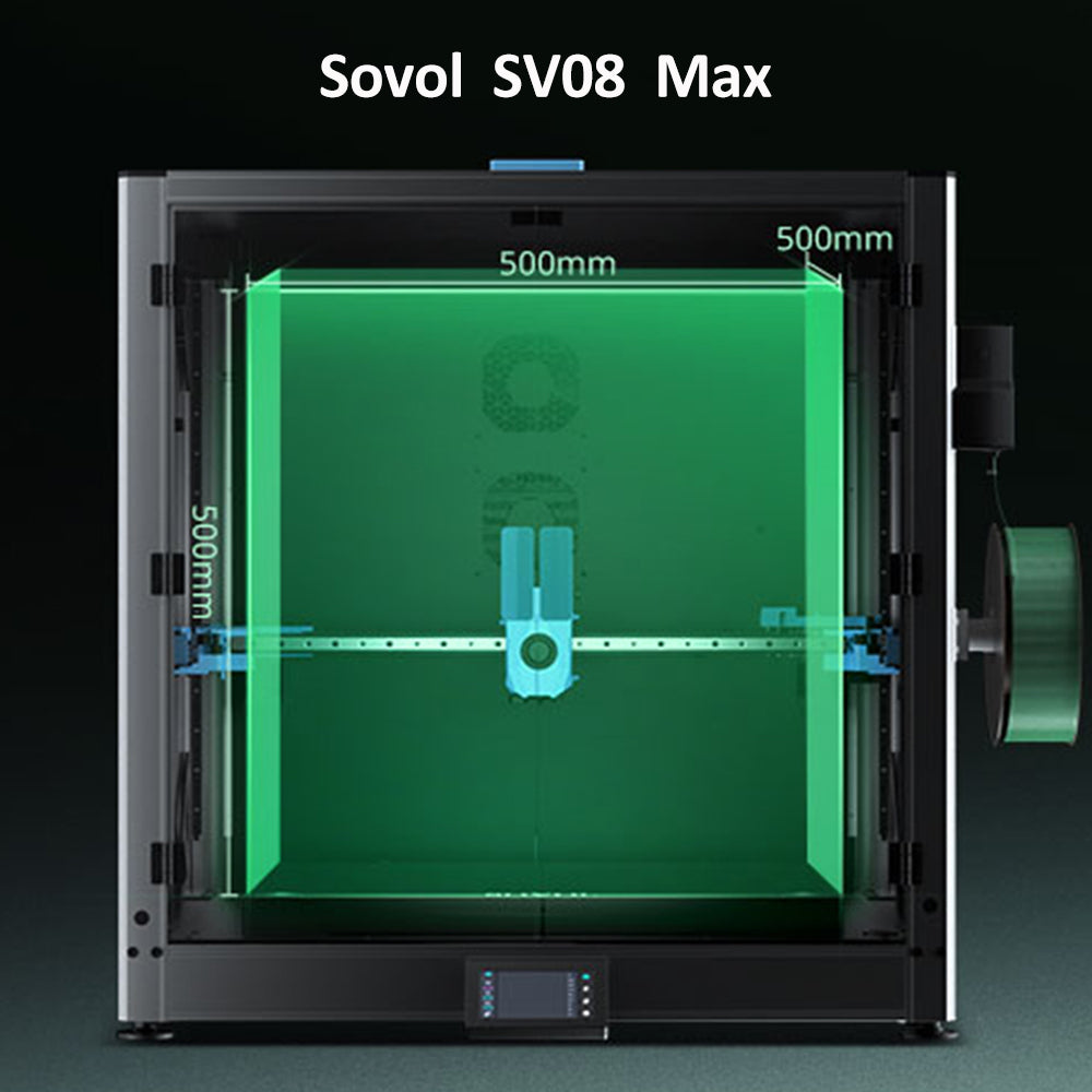
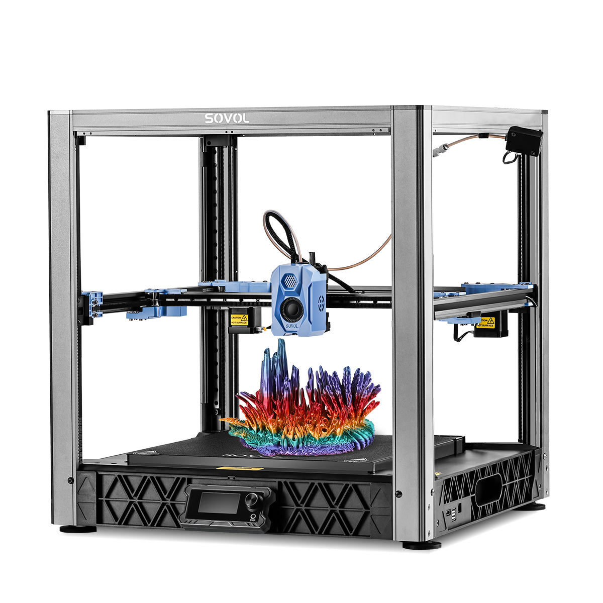
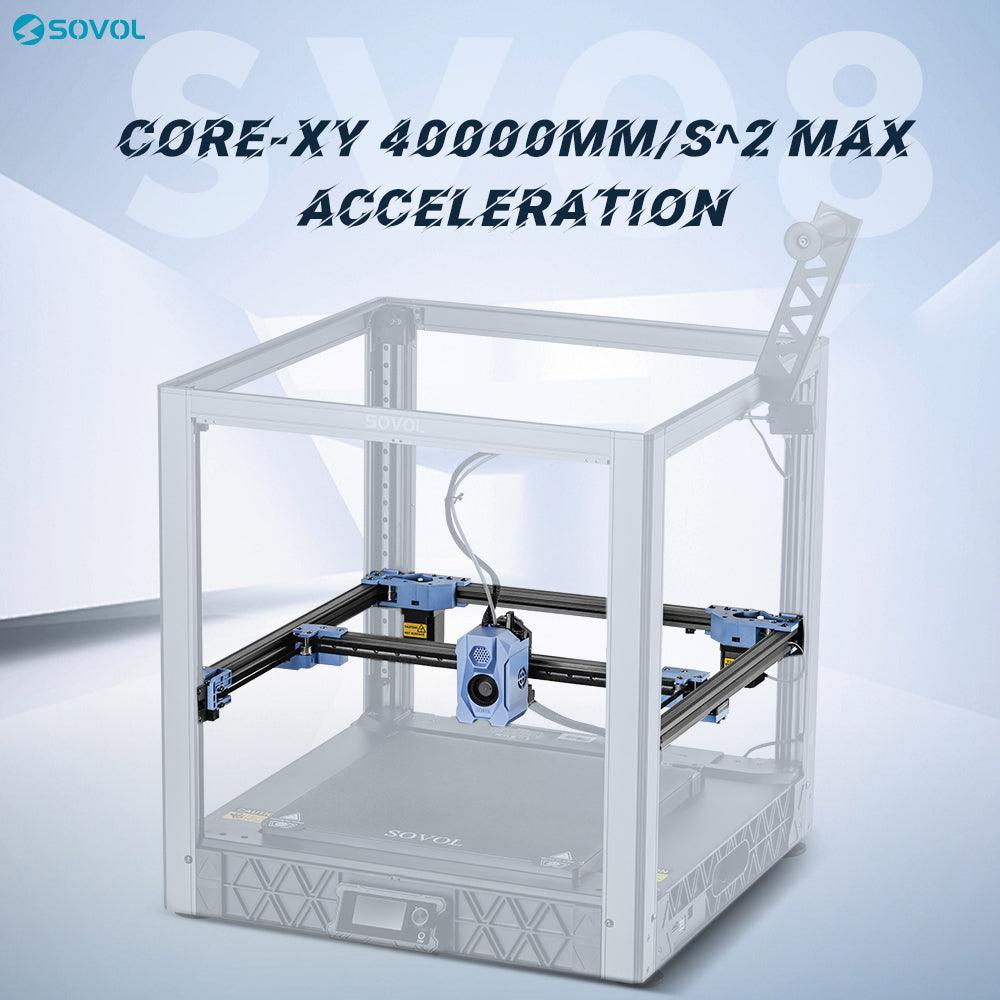
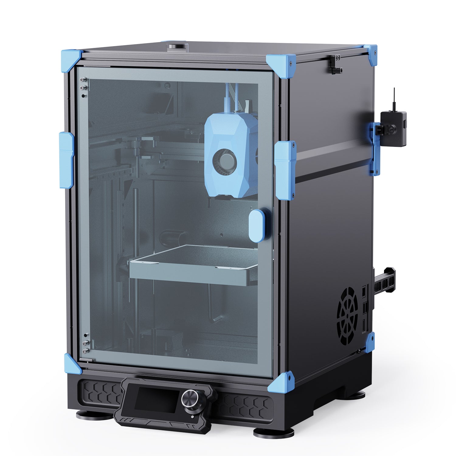
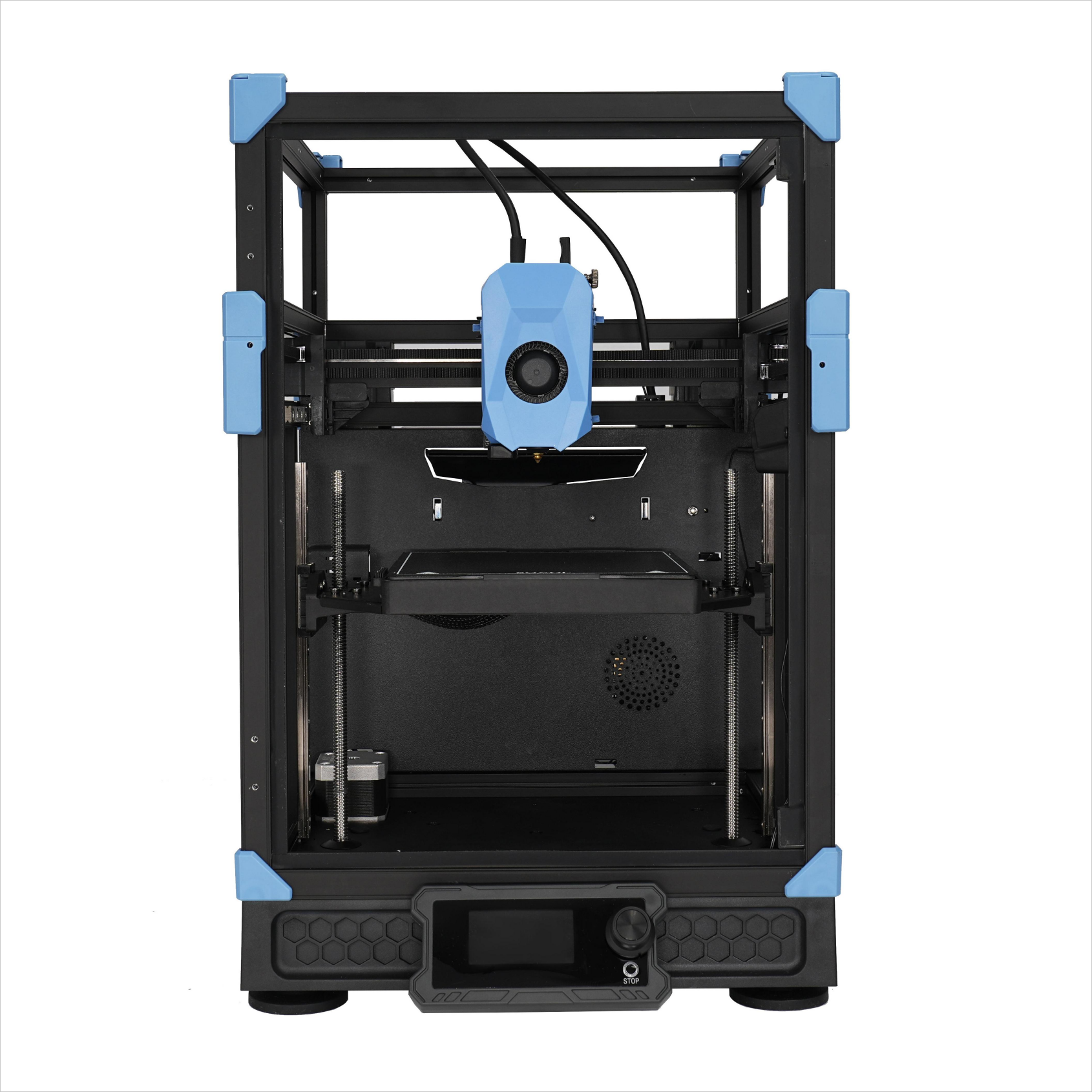
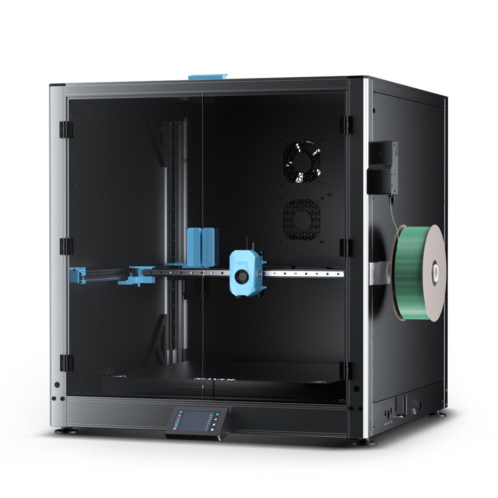
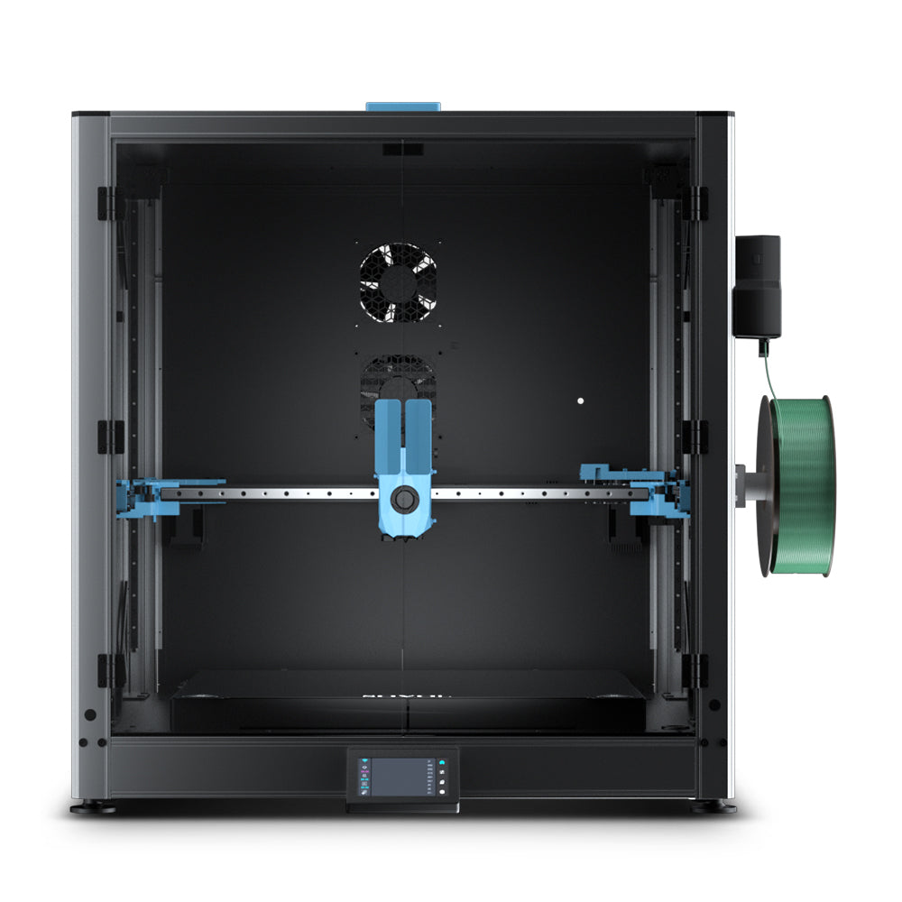
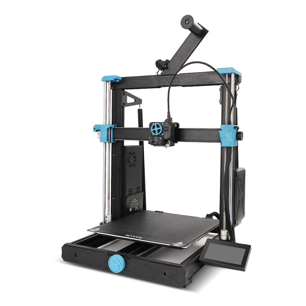
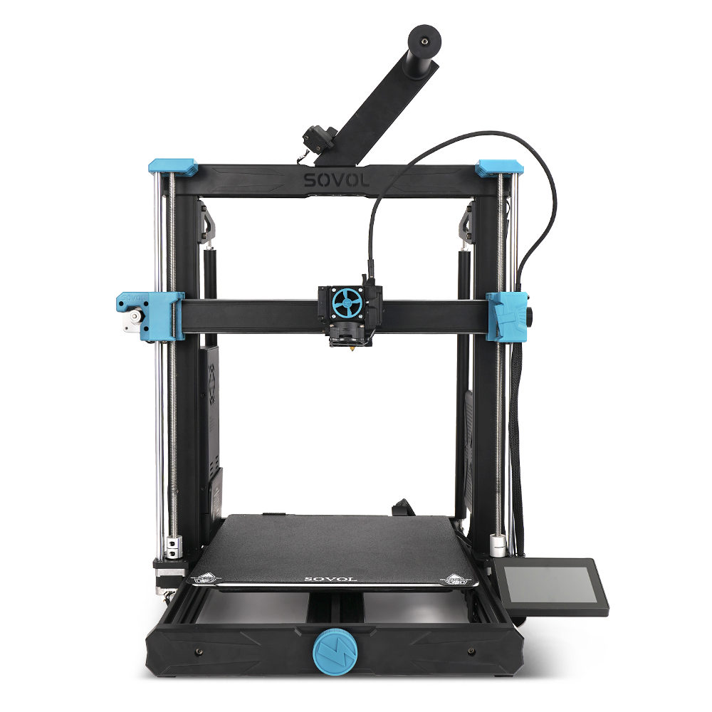
For reference, the Sovol SV08 has a 350×350×345 mm build volume, and the Sovol SV08 Max offers up to a 500×500×500 mm build volume (500×500×450 mm with the enclosure kit).
(Those build-volume specs come from the SV08 and SV08 Max product pages on sovol3d.com.)
Next steps
If you’re printing large models regularly (maker spaces and school labs especially), it can be worth reducing your seam count instead of perfecting seam repair.
- Explore larger build volumes: Sovol SV08 and Sovol SV08 Max
- Or keep going with multi-part prints: save this workflow as a checklist for your lab so new users can follow it consistently
